

Output Compare
Ein Output soll nach einer bestimmten Zeit togglen.
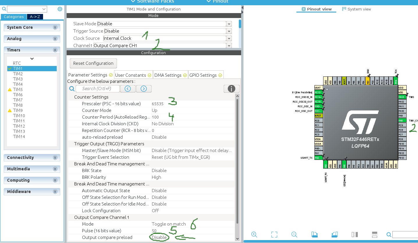
/* USER CODE BEGIN 2 */
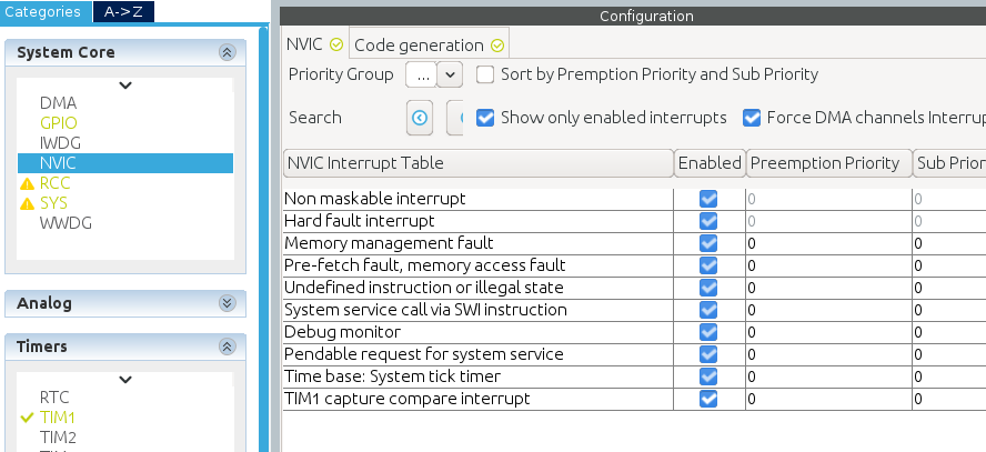
HAL_TIM_OC_Start_IT(&htim1, TIM_CHANNEL_1);
/* USER CODE END 2 */
PWM
Duty cycles:  where T is the pulse duration and P the period of the PWM signal
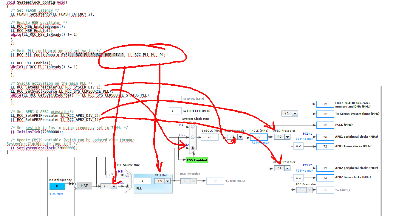
Clock System
LL (low level) Functions
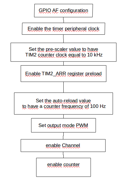
GPIO alternate function (AF) configuration
-
Enable the peripheral clock of GPIOs
Which clock? See Datasheet "CLOCK TREE" and "APB2 Peripheral Clock Enable Register"Functions start with LL_APB2_ … use auto completion
LL_APB2_GRP1_EnableClock(LL_APB2_GRP1_PERIPH_GPIOA); -
PinMode Alternate
LL_GPIO_SetPinMode(GPIOA, LL_GPIO_PIN_0, LL_GPIO_MODE_ALTERNATE); -
Pulldown/Frequency
LL_GPIO_SetPinPull(GPIOA, LL_GPIO_PIN_0, LL_GPIO_PULL_DOWN);
LL_GPIO_SetPinSpeed(GPIOA, LL_GPIO_PIN_0, LL_GPIO_SPEED_FREQ_HIGH);
General Purpose Timers
-
16bit autoreload, programmable prescaler
-
input capture (measure puls length of input signals)
-
output compare (generate Waveforms and PWM)
-
4 independant channels (IC,OC,PWM,Onepulse-Mode output)
-
Sync circuits for ext. signals
Interrupt on
Update: over-/underflow, counter init
Trigger event (start/stop, init, count int/ext trigger)
IC/OC
-
incremental encoder
-
Prescaler (16Bit)
Counter Modes
-
Upcounting
-
Downcounting mode
-
Center-aligned mode (up/down counting)
-
Master – Slave
Master-Slave Beispiel
Timer1 soll von Timer5 hochgezählt werden. Timer5 läuft im Sekundentakt über und löst für Timer1 ein Triggerereignis aus.
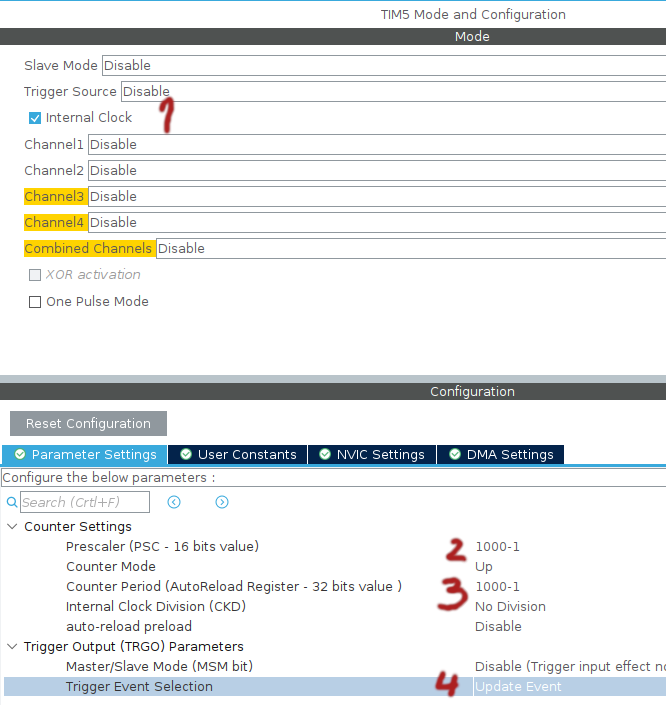
Trigger Event Selection
-
update event … reset, compare match
-
OC output compare … compare match
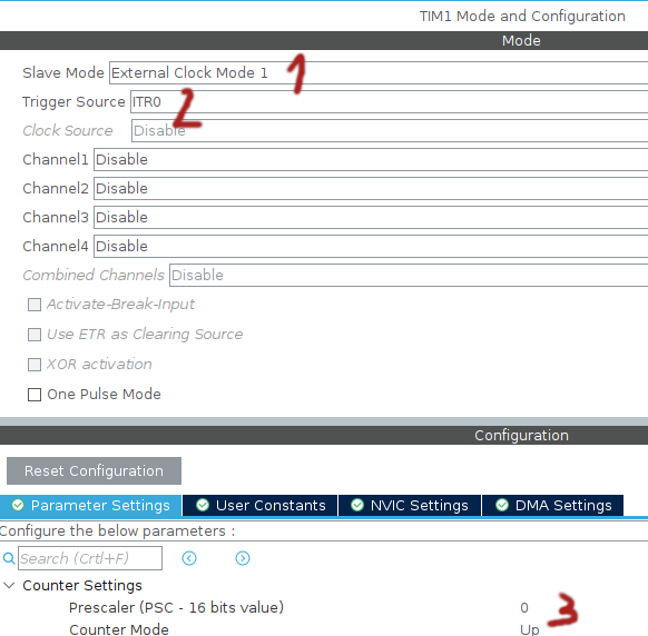
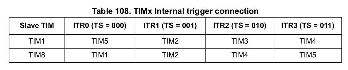
Nicht jeder Timer kann Timer1 triggern: